How to Make a Custom Silicone Soap Mold with Fusion and 3D Printing
⚙️ Affiliate Disclosure
Some banners or links on this page are affiliate links, meaning I may earn a small commission if you purchase through them — at no extra cost to you.
This helps support The Maker Letters and future Fusion tutorials.
🐝 How I Designed a Custom Silicone Honeycomb Mold in Fusion
Full video tutorial is embedded at the bottom of this post.
Custom molds are fun — and people actually buy them. In this project, I designed a silicone honeycomb mold from scratch using Fusion, 3D printing, and some simple but powerful modeling techniques. Along the way, I learned what works best for both casting and print quality.

A side-by-side comparison titled “Design and Reality” showing parts of the full workflow — parts of the digital 3D model created in Fusion, the silicon mold and the finished honeycomb soap. The photo highlights how the final handmade soap closely matches the original CAD design.
Start With a Digital Soap Model
Begin by following the first rule of Fusion: create a new activated component.
I started by modeling the soap itself — 60 by 85 millimeters, and 25 millimeters thick. This helps visualize the final cast and keeps the design parametric when we later build the mold.
Always build around the center of the origin to take full advantage of symmetry. It makes every edit faster.
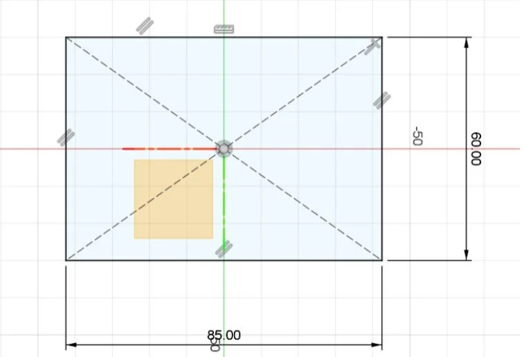
Sketching the base dimensions for the soap model in Fusion — 85 by 60 millimeters, centered on the origin to ensure symmetry throughout the design.
Sketching the Honeycomb Pattern
On the bottom face of the soap, use the circumscribed polygon tool to create the honeycomb.
A radius of 5 mm gives a good balance between pattern and shape. Add two construction lines at 30° angles to guide the pattern layout.
Use the Rectangular Pattern tool to fill the face symmetrically — spacing of 12 mm keeps a 2 mm gap between each cell. Once the pattern looks right, extrude it down by 2 mm to emboss the honeycomb into the soap.

Embossing the honeycomb pattern into the soap model by extruding the hexagonal sketch down 2 millimeters — creating the textured surface that will later transfer to the silicone mold.
Adding Chamfers and Fillets
Chamfers and fillets make the soap nicer to hold — but they also add strength and improve printability.
Separate bottom and side chamfers into different timeline features for easy parametric edits later.
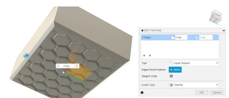
A 3D model in Fusion is shown from a bottom-angled view. The model features a honeycomb pattern, and a chamfer operation is being applied to the inner rectangular cutout at the center. A blue arrow indicates the chamfer direction, and the distance is set to 2 mm. On the right side of the image, the “Edit Feature” dialog is open, showing four selected edges with a 2 mm equal distance chamfer, the “Tangent Chain” option checked, and “Corner Type” set to “Chamfer
Building the Silicone Mold
Now it’s time to build the mold that will cast the soap.
Switch to the top component and create a new one named Silicone Mold.
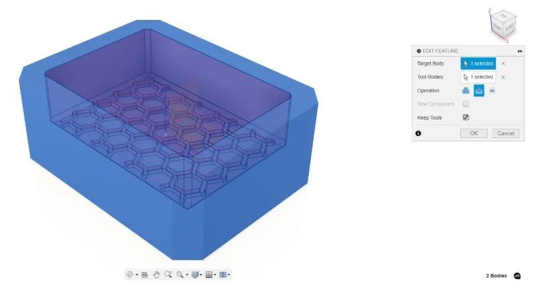
Project the soap outline into your new sketch so any changes stay linked. Offset the outline by 10 mm — that’s a solid silicone thickness. Then extrude the shape so it completely covers the soap model.
Use Combine → Cut with the soap as the tool body. Keep the tool so we can reuse the soap later.
When you hide the soap component, you’ll see the mold cavity ready for casting.
A bottom view of a 3D model in Fusion shows a rectangular cutout centered within a honeycomb pattern. A chamfer tool is active, indicated by a blue arrow pointing along the selected edges. The chamfer distance is set to 2 mm. On the right side, the “Edit Feature” panel is open, listing four selected edges with equal distance chamfers of 2 mm. The “Tangent Chain” option is checked, and the corner type is set to “Chamfer.
Creating the 3D-Printed Mold Base
Next, we’ll design the 3D-printed mold base — the part that holds everything during casting.
Create a new component called Mold Base.
Use Surface → Offset on all faces of the silicone mold (set to 0 mm). Then Thicken it to 10 mm to make a solid base.
Turn the silicone mold visibility back on — it should fit perfectly inside the base.
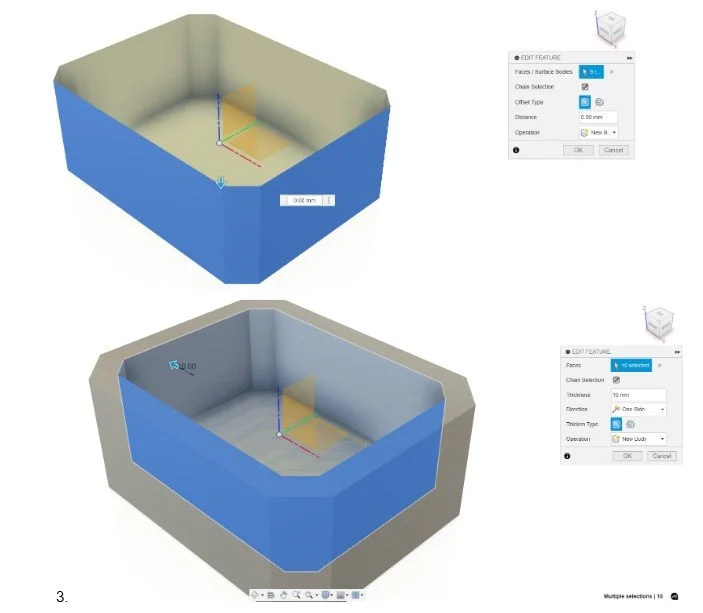
The image shows two stages of creating a mold body in Fusion.
In the top image, the inner faces of a rectangular cavity are selected, and the Offset Faces tool is active. The offset distance is set to 0 mm, and the operation is set to New Body.
In the bottom image, the newly created surface body is selected, and the Thicken tool is being used. Ten faces are selected, the thickness is set to 10 mm, with the direction set to One Side. The operation is also set to New Body, which will create a solid mold structure from the surface.
Designing the Mold Top
Create another component named Mold Top. This will press down on the silicone mold when casting.
Sketch it on top of the soap component, keeping things simple for the first iteration. A 5 mm thickness is a good starting point.
Duplicate the part and rotate it 45°. Then use Extrude to adapt the edges to the base.
Add cylinders (5 mm diameter) to align the mold top precisely. Instead of cutting right away, set them as New Bodies first.
Use the Mirror tool with the origin planes to duplicate them symmetrically — a neat, time-saving trick that updates automatically when you change dimensions.
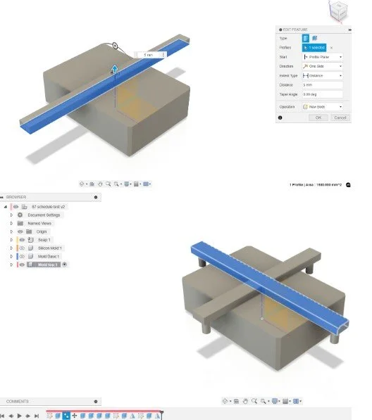
The image shows the creation of support bars designed to keep the mold top elevated above the mold base in Fusion.
In the top image, a rectangular profile is being extruded with a distance of 5 mm. The direction is set to One Side, and the operation is New Body, creating a tapered bar that spans across the mold.
In the bottom image, two perpendicular support bars are visible, crossing each other above the mold base. These bars will serve as spacers to maintain a consistent gap between the mold top and base during casting.
Preparing for 3D Printing
Make the parts printable.
Since the honeycomb pattern sits at the bottom, print the soap and mold top upside down. Flatten the top surface to avoid supports — a simple Project + Extrude Join gets it done.
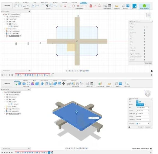
The image shows the process of designing and extruding the mold top in Fusion.
In the top image, a sketch is open in the Sketch workspace, displaying a cross-shaped support structure centered on the origin. This sketch will define the base of the mold top, with intersecting rectangles forming a stable grid.
In the bottom image, the sketch profile is being extruded upward with a distance of 25 mm. The operation is set to New Body, creating the main solid body for the mold top, including the integrated cross-shaped supports.
Cutting Holes and Adding Clearance
When all cylinders are placed, use Combine → Cut to make holes in the mold base.
Check Keep Tools so you can still use the cylinders later.
If the clearance looks too tight, apply Offset Face to the holes — I used 0.5 mm, which fits perfectly for FDM 3D printing tolerances.
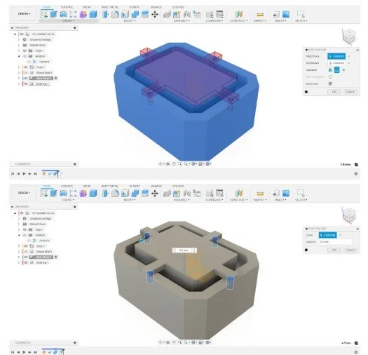
The image shows the process of using the Combine tool in Fusion to cut alignment features into the mold base.
In the top image, the mold top is highlighted in blue and set as the Tool Body, while the mold base is the Target Body. The operation is set to Cut, and the Keep Tools option is enabled.
In the bottom image, the result of the combine operation is visible. Four circular alignment posts have been cut into the mold base, creating matching recesses. These alignment features will help position the mold top accurately on the base.
Exporting STL Files
Two export workflows to remember:
Mold Base: right-click → Save as Mesh → choose STL → save.
Soap + Mold Top: make both visible, hide others, and export via File → 3D Print (also as STL).
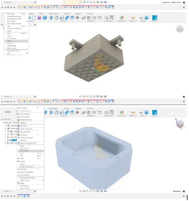
The image shows the final preparation steps for exporting the mold components in Fusion.
In the top image, the mold top is shown from a bottom perspective, displaying the honeycomb pattern. The File menu is open, highlighting the Save as Mesh option. This indicates the mold top is being prepared for export as an STL or similar mesh format for 3D printing.
In the bottom image, the mold base is selected in the Browser, and a right-click menu is open with the Save as Mesh option highlighted. This shows the same export process being applied to the mold base, allowing both parts to be saved individually for printing.
Slicing and Printing Tips
In PrusaSlicer, the mold base imports perfectly oriented.
Enable Ironing to smooth the top layer and minimize print lines — it increases print time slightly, but the surface quality improves a lot.
For infill, I used 15 %. That was enough to keep the mold leak-proof while keeping the print time manageable.
On my Original Prusa i3 MK3S+, the mold base took 6 hours 44 minutes, but newer printers will be faster.
Before slicing, flip the combined soap + mold top upside down. Use ironing here too — it helps reduce visible lines not only on the 3D print, but also on the silicone mold and eventually on the soap itself.
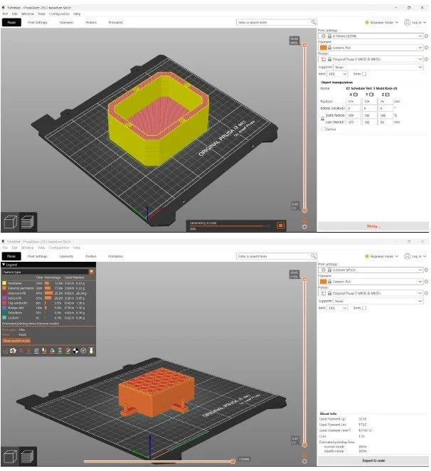
The image shows the mold components prepared for 3D printing in PrusaSlicer.
In the top image, the mold base is positioned on the print bed. The model is sliced and previewed with yellow walls and red infill, indicating different print features. On the right, the printer and filament settings are configured for an Original Prusa i3 MK3S+ using Generic PLA at 0.15 mm layer height.
In the bottom image, the mold top with the honeycomb pattern is placed on the build plate. The slicing preview shows internal structure and support bars. Print settings are visible on the right, and on the left, the sliced file information includes estimated print time, filament usage, and weight.
Wrapping Up
This workflow connects every stage — digital model → silicone mold → 3D print → final cast.
By linking sketches and keeping features parametric, you can tweak sizes or adjust patterns and regenerate everything automatically.
I was genuinely surprised by how well this first mold performed, and it opened up new possibilities for both hobby and small-business projects.
Scroll down to watch the full step-by-step video 👇
Step-by-step guide to follow along in Fusion
00:10 Start Your Fusion Project with a New Component
00:33 Build a Center-Based Sketch for Symmetrical Design
01:02 Create a Honeycomb Pattern in Fusion (Perfect for Soap or Mold Designs)
02:48 Extrude the Honeycomb Pattern into a Solid Model in Fusion
03:39 Add Chamfers and Fillets for a More Refined Mold Design
04:09 Design the Silicone Mold Geometry in Fusion
04:30 Reuse Existing Sketch Lines Efficiently in Fusion
05:19 Use the Combine Command to Cut Away Parts in Fusion
05:45 Design the 3D Printed Mold That Will Cast the Silicone Mold
06:13 Offset Faces in Fusion to Prepare for Mold Wall Thickness
06:39 Thicken Surfaces to Convert Your Mold Design into a Solid Body
07:15 Model the Top Part of the 3D Printed Mold for Silicone Casting
08:05 Copy and Rotate Bodies to Complete Your Mold Assembly
08:18 Shorten a Body Using the Extrude Command in Fusion
09:21 Mirror Bodies in Fusion for a Symmetrical 3D Printed Mold
10:35 Cut Holes and Adjust Clearances for FDM 3D Printing Tolerances
11:37 Fine-Tune Your Mold Design for Successful 3D Printing
12:32 Inspect the Mold with Section Analysis in Fusion
13:09 Export Your Design: Best Practices for STL and Mesh Files in Fusion
13:58 Slice Your 3D Printed Mold in PrusaSlicer — Setup and Tips
This project was created and recorded on my Lenovo ThinkPad (2019) — a reliable laptop that has handled all my Fusion design work smoothly. I recorded and edited the screen captures using Camtasia, which makes it easy to produce clear and structured tutorials. Both tools have been essential in bringing this project together from start to finish.