How to Design and 3D Print a Sillcock Key in Fusion
The full Fusion tutorial is linked at the bottom of this post.
In this project, we’ll walk through how to design and 3D print a sillcock key using Fusion. The workflow combines solid, surface, and form modeling, showing how powerful Fusion becomes when you use different environments together.
Starting the Design
Begin with Fusion’s first rule: create a new component. With Activate checked, you’ll be working inside it right away.
Next, open a sketch on the horizontal construction plane and draw a center rectangle. I set mine to 10.5 × 10.5 mm, based on measurements taken with a digital caliper from an existing sillcock key.
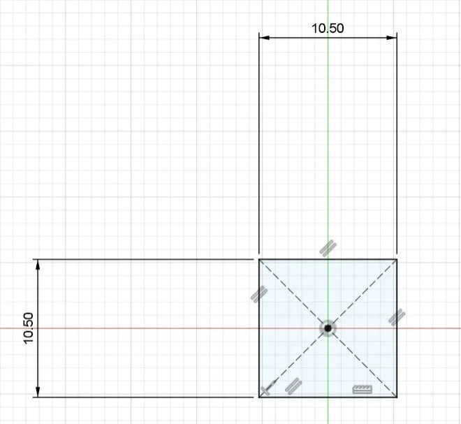
Make a center rectangle sketch
Building the Base
Use the Surface Extrude command to turn the rectangle into an infinitely thin surface. This method gives flexibility later when refining the model. Thicken the surface by –1 mm (or adjust to fit your needs).
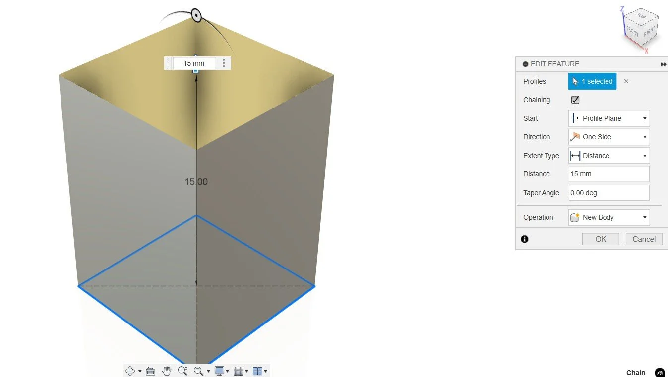
Use surface modeling to extrude a thin rectangle

Thicken your surface model 1 mm
To improve strength and usability, add fillets to the edges. The Orbit tool makes it easy to select everything at once, and capturing the fillets as a single timeline action keeps future edits simple.

Fillet all edges 1 mm
Creating the Top
Set an offset plane 20 mm above the base and sketch another center rectangle, this time sized at 17.5 × 35 mm. Starting sketches from the origin makes adjustments easier later.

Create an offset plane for your next sketch
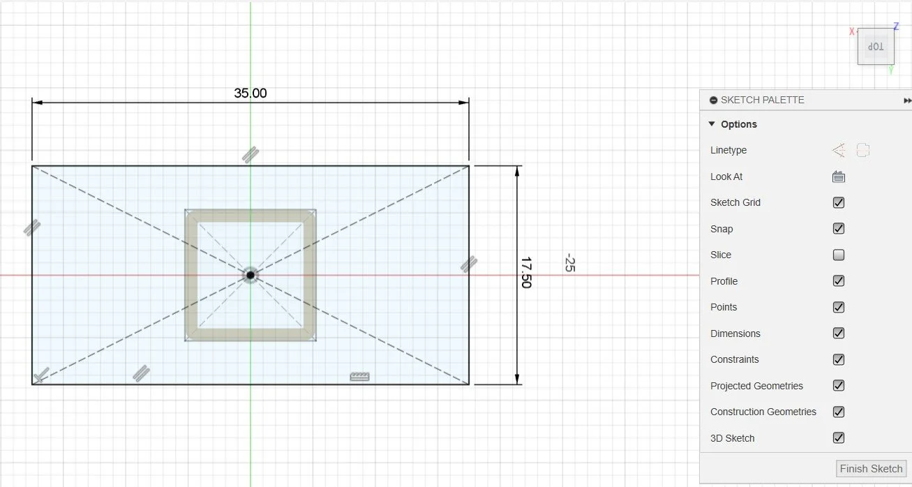
Create a new Center Rectangle Sketch on your new Offset Plane
Jump directly into the Extrude command by pressing E and pull the sketch 3 mm downward toward the base.

Extrude your sketch -3 mm
Closing and Strengthening
Switch to the surface environment and use the Patch tool to close the top of the first model. Since patches have no thickness, convert it into a solid using an Extrude Join operation. This step ensures the part has strength and is ready for manufacturing.

Close the top with the Patch tool
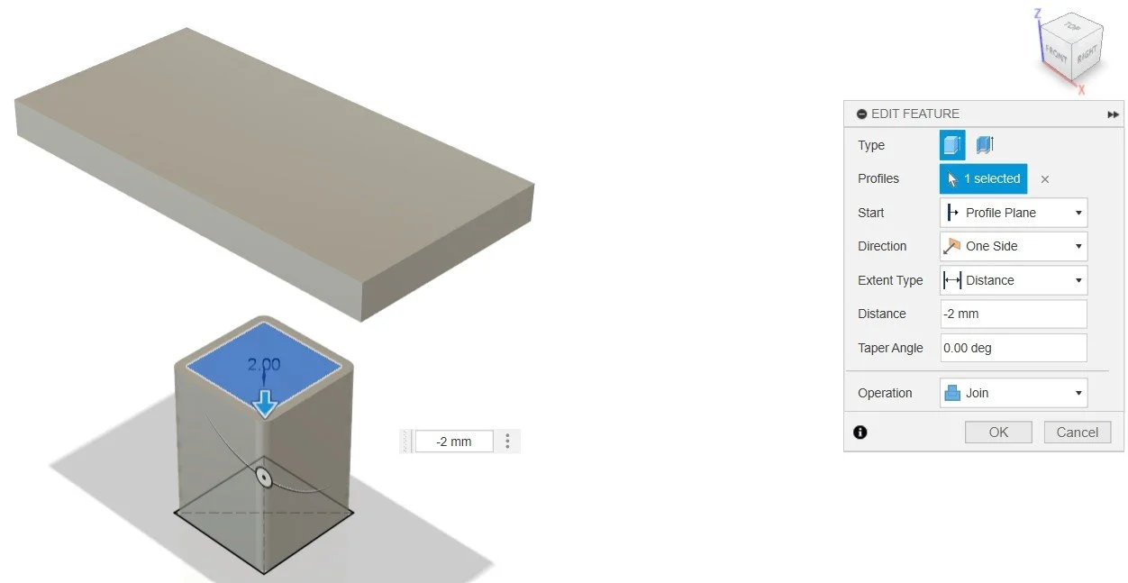
Extrude the patch -2 mm and set the operation type to Join
Adding the Twist
Now it’s time to connect the top and bottom. Activate 3D Sketch and draw guide rails on the vertical plane. Straight lines work for this project, but arcs or splines can give creative variations. Connect each filleted corner from the base to the top rectangle. Orbit the model as you go to check that all the lines snap correctly. Close the sketch once all four corners are connected.
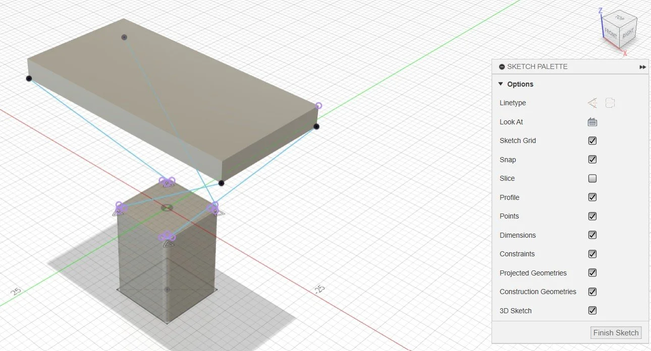
Activate 3D sketch and connect the bottom and the top
Save the project at this stage and add a version description. It’s good practice before running more advanced operations.
With the profiles and rails ready, use the Loft tool to connect the shapes. Adding rails introduces a twist to the design. Inspect the model from different angles to confirm everything looks right.
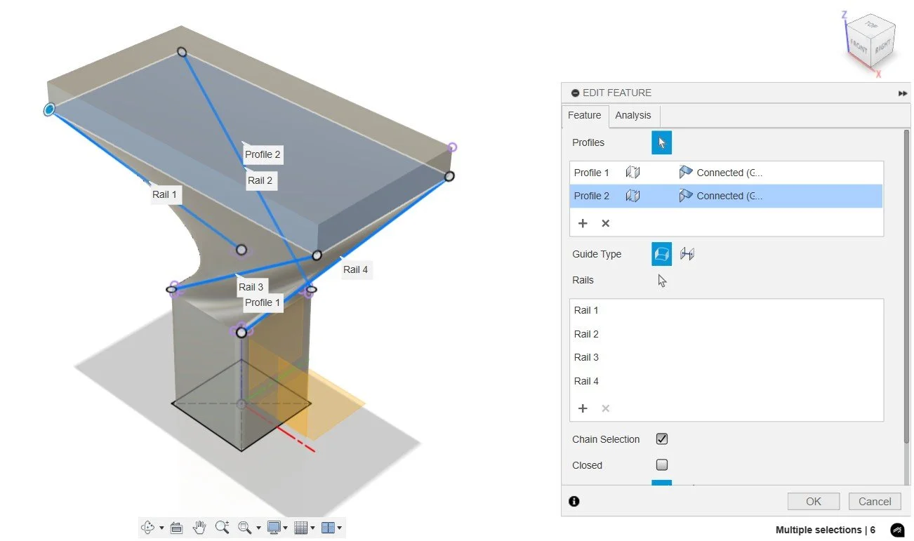
Loft with Guide Rails
Refining the Design
Add another round of fillets to smooth out sharp areas. These improve both comfort and appearance.

Fillet the edges for a better user experience
For ergonomics, we’ll also add a thumb rest. Switch to the Form environment, create a simple box on top of the sillcock key, and enable symmetry so it can be adjusted evenly. This form body then acts as a cutting tool—use Combine Cut to remove material and shape the rest area.

Create a box in the form modeling environment

Remove material with a combine cut operation
Preparing for 3D Printing
Once the design is ready, export it as an STL file using Save as Mesh.
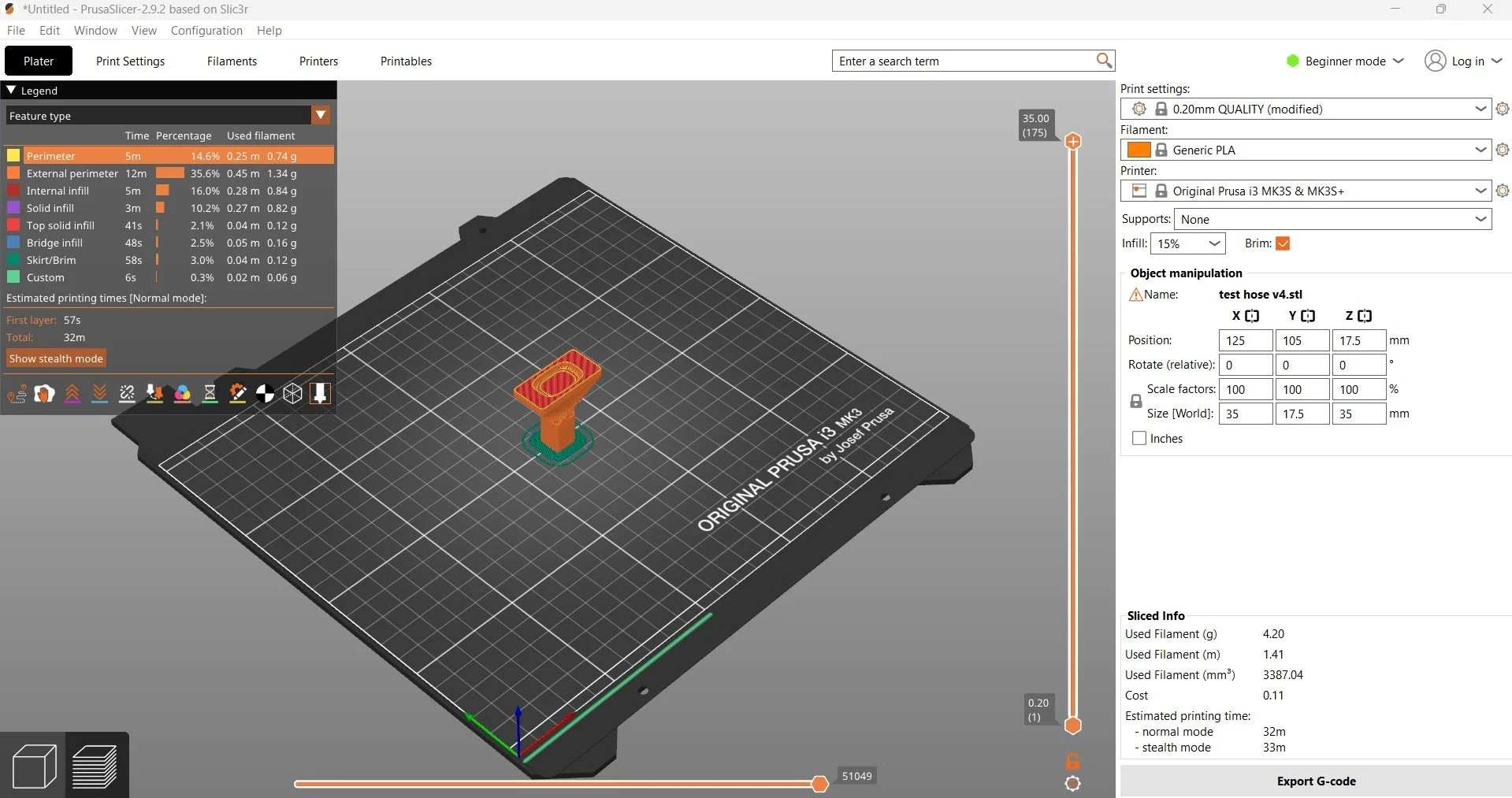
Open the STL in your slicer (PrusaSlicer in this example). Since the key has a small contact area with the build plate, add a brim to improve stability. I used the default quality preset and standard infill.

Add Brim for better Adhesion
Export your G-code
For prototyping, PLA works fine, but remember it’s brittle. Stronger materials are recommended for a functional sillcock key.
Final Result
The print came out great, and now I can produce as many sillcock keys as I need. This workflow shows how surface, solid, and form modeling can be combined efficiently inside Fusion.
Disclaimer: All projects, designs, and tutorials are shared for educational and informational purposes only. Use them at your own risk. I make no guarantees of safety, functionality, or fitness for a particular purpose.
This project is not sponsored, approved, or associated with Autodesk, Prusa, or any other company mentioned. All rights, trademarks, and intellectual property belong to their respective owners. I am not responsible for any damage, injury, or loss resulting from the use of these projects.
Chapters in this Fusion tutorial:
00:09 Fusion – Create New Component in Browser
00:24 Fusion Sketch – Center Rectangle on Construction Plane
00:55 Fusion Surface Extrude – Create Base Shape
01:16 Fusion – Thicken Surface into Solid
01:27 Fusion – Add Fillet to Solid Model
01:49 Fusion – Create Offset Plane for Second Sketch
02:09 Fusion Sketch – Center Rectangle on Offset Plane
02:45 Fusion Solid Extrude – Build Second Shape
03:02 Fusion Patch Tool – Close Top Surface
03:20 Fusion Extrude Join – Convert Patch to Solid
03:43 Fusion 3D Sketch – Setup for Loft Command
04:46 Save Project – Add Version Description in Fusion
04:56 Fusion Loft – Use Guide Rails for Smooth Connection
05:35 Fusion – Add Fillets for Design & Ergonomics
05:55 Fusion Form Environment – Create Box Shape
06:33 Fusion Combine Cut – Remove Material
06:58 Export Fusion Model as STL Mesh File
07:17 PrusaSlicer – Import STL & Add Brim before G-Code
07:57 Conclusion – Fusion Modeling & 3D Printing Tips