How to Create a Fan Grille with a Honeycomb Pattern in Fusion
Updated February 21, 2026
What You’ll Learn
- How to structure a Fusion project using components and clean sketch setup
- Why modeling a single feature first improves flexibility and scalability
- How to build and control a honeycomb pattern using sketch patterns and construction geometry
- When to extrude negative space instead of solid profiles for better results
- How to use the Project tool to maintain parametric relationships between sketches
- How to create efficient rectangular patterns using faces instead of features
- When to apply fillets in the timeline for stability and control
- How to introduce curvature using splines and surface-based workflows
- How to use Revolve Cut to cleanly trim complex geometry
- How to structure bodies for easier visualization, rendering, and multi-color 3D printing
Watch the Workflow — or Read It Step by Step
You can follow this guide in two ways:
- Read the steps below if you want quick written instructions, reference images, and modeling notes.
- Watch the full video at the end of this post to see the workflow in real time — including extra tips, camera angles, and shortcuts that don’t fit neatly into text.
Both formats build on each other.
Reading helps you understand why each step matters, while watching shows how to move faster in Fusion.
Step 1: Setting Up the Component and Sketch
Start by creating a new, activated component. Then, create a sketch to define the boundaries of your grille. Using a center rectangle keeps the design centralized above the origin. Set dimensions to 120 × 120 mm, but adjust them as needed.
New component setup in fusion for honeycomb ventilation grille project.
Center rectangle sketch with 120 mm dimensions aligned to origin grid.
Next, sketch a single hole instead of four, as solid modeling features will generate the others. This keeps the design flexible. Add dimensions for quality control and easier pattern creation later. Also, create a center-diameter circle in the middle—this will serve multiple purposes.
Single hole placement with dimensions for controlled pattern creation.
Design shortcut used to quickly create and finish a center-diameter circle as reference geometry for the grille layout
Step 2: Creating the Honeycomb Pattern Sketch
Start a second sketch to isolate the honeycomb pattern. Use the same construction plane as before. Sketch a circumscribed polygon at the center, then add two construction lines: one vertical and one at a 45-degree angle. Convert them into construction lines to avoid interference.
Hexagon polygon with vertical and angled construction lines for pattern direction.
Select the Rectangular Pattern tool designed for sketches. Choose the polygon first, then use the two construction lines as direction guides. Set the spacing slightly over 10 mm to ensure a well-proportioned pattern and use the Symmetric option for direction.
This separate sketch approach allows for oversketching and refining the pattern later.
Honeycomb sketch created using rectangular pattern with symmetric spacing
Step 3: Preparing the Extrusions
Instead of extruding the polygons, extrude the area between them. Use the Project tool to link the circle from Sketch 1 into Sketch 2 to align elements.
Base extrusion of square profile with circular cutout in solid modeling workspace
Now, extrude the area between the rectangle and the circle from Sketch 1 to 10 mm. Hide Body 1, turn on Sketch 2, and ensure the projected circle is a regular line (not a construction line). Then, extrude the honeycomb pattern up to Body 1’s top to maintain adaptability in the Fusion timeline. Set this as a New Body operation for flexibility.
Honeycomb pattern extruded as separate body aligned to base geometry.
Step 4: Creating the Rectangular Pattern for Holes
Before adding complexity, create the rectangular pattern for the holes while the model remains simple. Set the object type to Faces and select the hole’s face. Use both axes to distribute the pattern evenly. Since the total width is 120 mm with a 10 mm edge gap, setting the total extent to 100 mm ensures even spacing.
Rectangular pattern applied to hole faces for evenly spaced mounting holes.
Step 5: Adding Fillets for Smooth Corners
Filleting early keeps the process simple before adding curvature. Select all sides, switch to the Top View, and apply the fillet. This step can be adjusted later in the timeline.
Think about the pros and cons of filleting now versus later.
Fillet applied to outer edges with 5 mm radius for smoother corners
Step 6: Adding the Curved Shape
Create a new sketch on the central construction plane. Use the Fit Point Spline to design a smooth curve. The green handlebars help refine the curvature. Extend the spline beyond the model to cover the corners in the next step.
Fit point spline used to define curved side profile for grille shape.
Extrude the spline minimally to create a surface for thickening. Then, use a Revolve Cut operation to trim away parts around the model, ensuring the corners are cut properly.
Spline profile extruded to create surface used for curved geometry
Surface thickened into solid body using thicken command
Revolve cut used to trim curved geometry around grille body.
Step 7: Finalizing and Exporting
Creating the grille around the central axis makes selections fast and precise. Hide any unnecessary parts and explore appearance options. A glossy plastic look works well and is 3D printable.
Since the honeycomb pattern was created as a separate body, you can color each body differently if needed.
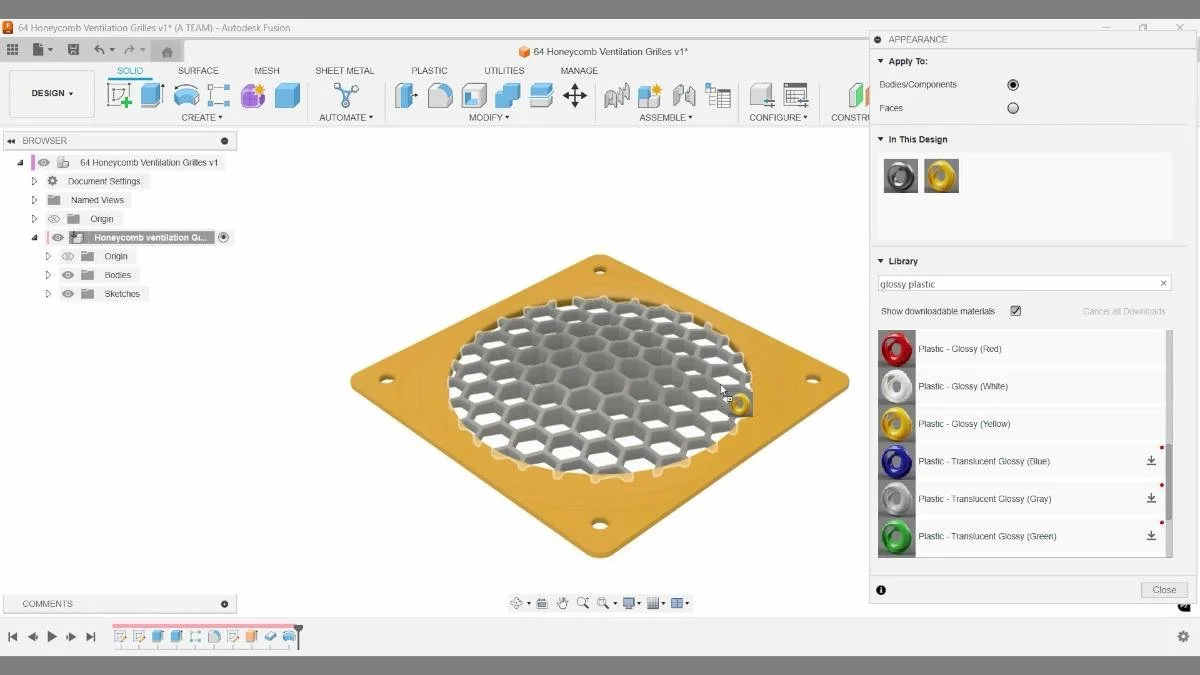
Final render of honeycomb ventilation grille with glossy plastic appearance for 3d printing.
Key Takeaways
- Use center-diameter circles to control layout and maintain symmetry around the origin
- Build reference geometry early to guide downstream features and patterns
- Create one clean hexagon and reuse it with rectangular pattern for efficiency
- Use project to link sketches and keep geometry parametric and consistent
- Separate sketches for base geometry and pattern improves control and edits
- Extrude patterns carefully to ensure clean, printable cut-through geometry
- Apply fillets to improve both aesthetics and printability
- Combine surface and solid tools for more flexible shaping workflows
- Use revolve cut and spline-based profiles to refine organic transitions
- Finalize with appearance tools to visualize the design before printing
🧰 Tools & Deals
I’ve gathered some of the tools, software, and gear I personally use and recommend for CAD work, 3D printing, and making things in one place. Some links may include discounts or special offers that can help you level up your workflows.
Please note: some of the links are affiliate links, which means I may earn a small commission at no extra cost to you. This helps support the site and the creation of free Fusion tutorials.
Explore everything here:
The Maker Letters – Tools & Deals
.
Chapters:
00:10 How to Create a New Component in Fusion
00:22 Creating a Center Diameter Circle Above the Origin in Fusion
00:57 How to Create a Circle for Holes Around the Grill in Fusion
01:20 Setting Up a Center Diameter Circle for Precision in Fusion
01:32 How to Set Up the Second Sketch for Honeycomb Pattern in Fusion
01:50 Creating a Polygon for Honeycomb Pattern in Fusion
04:04 How to Use the Project Tool in Fusion to Link Sketches
04:41 How to Extrude a Sketch in Fusion for Solid Modeling
05:05 Extruding the Honeycomb Pattern in Fusion for 3D Printing
05:57 How to Create a Rectangular Pattern in Fusion
06:41 How to Apply a Fillet in Fusion for Smooth Edges
07:19 How to Create a Fit Point Spline in Fusion for Curves
08:21 How to Extrude a Line and Thicken a Surface in Fusion
08:53 How to Cut Away Parts Using Revolve Cut in Fusion
09:30 How to Add an Appearance to Your Model in Fusion
You Might Also Like
If you enjoyed this Fusion tutorial, here are three more projects that explore decorative CAD workflows, pattern-based design, and building clean, 3D-printable parts in Fusion.
Together, these tutorials expand on the same core ideas used here — building repeatable patterns, combining modeling techniques, and creating structured designs that translate cleanly into reliable 3D prints.