How to Model a Twisted Vase in Fusion Using Form, Surface, and Solid Modeling
Updated March 19, 2026
Combining different modeling environments in Fusion opens up far more creative possibilities than relying on just one workflow. In this project, you’ll create a twisted vase using Form modeling, convert it through Surface modeling, and finish it in the Solid environment. The result is a clean, parametric model that is ready for rendering and 3D printing.
What You’ll Learn
- How to start a Form modeling project using a cylinder primitive
- Why centering models at the origin simplifies parametric workflows
- How circular symmetry speeds up editing in Form modeling
- A practical workflow for twisting geometry using Edit Form and rotation
- How to convert a T-Spline form into a solid body using Patch and Stitch
- When to use Shell and Full Round Fillet for 3D-printable geometry
- Tips for rendering your design using Fusion’s cloud rendering tools
Watch the Workflow — or Read It Step by Step
You can follow this guide in two ways:
- Read the steps below if you want quick written instructions, reference images, and modeling notes.
- Watch the full video at the end of this post to see the workflow in real time — including extra tips, camera angles, and shortcuts that don’t fit neatly into text.
Both formats build on each other.
Reading helps you understand why each step matters, while watching shows how to move faster in Fusion.
Step 1 – Start a Form Modeling Cylinder
Begin by creating a new component and entering the Form modeling environment. Form modeling uses T-Spline geometry, which is extremely flexible and ideal for sculpting organic shapes like vases.
New component is created before entering the Form workspace to isolate the vase geometry and keep the timeline structured for modeling.
The S-key shortcut menu is used to quickly access the Create Form command, speeding up workflow compared to navigating the toolbar.
Insert a Cylinder primitive and center it at the origin on the horizontal construction plane.
Centering geometry around the origin is a useful habit in parametric CAD workflows. It keeps models predictable when you later use patterns, mirroring, or assemblies.
A cylinder primitive is placed at the origin to establish the base geometry for the vase in the Form environment.
Set the initial dimensions:
- Diameter: 50 mm
- Height: 100 mm
Cylinder dimensions and face counts are adjusted to control resolution. Visual style is changed to improve edge visibility, making it easier to read the form structure and shape the vase accurately.
These dimensions simply establish a starting point. One advantage of the Form environment is that you can reshape the geometry easily without needing to rebuild sketches.
Switch the display mode to Shaded with Hidden Edges. This makes it easier to see underlying edges and faces, which helps when selecting geometry later.
Increase the height faces and enable Circular Symmetry.
More faces provide additional control points, allowing you to sculpt the shape smoothly. Circular symmetry ensures that edits remain consistent around the vase’s axis.
Increasing height and diameter faces adds more control points, enabling smoother deformation when shaping the vase.
Step 2 – Modify Faces Using Edit Form
Now start shaping the cylinder.
Select multiple faces by holding Ctrl while clicking. Because circular symmetry is enabled, the corresponding faces around the cylinder are automatically selected as well.
Activate Modify → Edit Form and pull the selected faces outward.
Working with symmetric selections saves time and maintains precision. Instead of editing each section individually, the symmetry setting ensures the entire model updates consistently.
This is especially useful when modeling rotational objects such as vases, bottles, or containers.
Faces are moved using Edit Form to define the initial curvature and taper of the vase body.
Step 3 – Adjust Edges for Additional Shape Control
Next, select the green edge loops around the cylinder.
Again, hold Ctrl to select multiple edges and use Edit Form to pull them outward slightly.
Edge loops define how the surface flows between faces. Adjusting them allows you to refine curvature without dramatically changing the entire model.
Small adjustments at this stage can significantly improve the overall proportions of the design.
Vertical edges are adjusted to refine curvature and avoid uneven surface transitions in the form model.
Step 4 – Twist the Vase with Transform Rotation
With the base shape established, begin twisting the vase.
Select a group of height faces and open Modify → Edit Form.
Change the Transform mode to Multi, then rotate the selected faces.
In this tutorial, each segment is rotated 30 degrees. Repeating this workflow with different face selections gradually creates the twisted form.
The key idea here is incremental changes:
- select a smaller segment
- apply the same rotation
- repeat
This creates a smooth transition rather than a sharp twist.
Another approach would be to drive the rotation using user parameters, which allows you to adjust the twist later through a single value.
The vase body is twisted by rotating selected geometry, creating the characteristic spiral surface.
The top edge loop is scaled to define the opening size and improve proportions of the vase.
Step 5 – Decide the Final Top Rotation
The final height segment presents a design choice.
You can either:
- leave the top section straight
- rotate it to continue the twist
Both approaches work, depending on the aesthetic you prefer. In this tutorial the top section is rotated to maintain the continuous spiral form.
One advantage of the Form environment is how quickly you can experiment. Small variations in rotation angles can lead to dramatically different designs.
The top ring of faces is selected to isolate the opening region for controlled deformation.
Edge and face adjustments smooth the rim to remove sharp transitions and create a more organic shape.
Step 6 – Convert the Form Model to a Surface
When you exit the Form environment, the model becomes a surface body.
Surface bodies represent geometry with zero thickness. They are perfect for sculpting shapes but cannot be printed or manufactured until converted into a solid.
To close the model, use the Patch command.
Patch the openings at the top and bottom of the vase.
A useful shortcut here is Repeat Patch, available through the right-click menu, which quickly repeats the last command.
A Patch surface is applied to close the bottom opening, converting the form into a watertight surface body.
The top opening is temporarily patched to enable further surface operations and ensure clean geometry.
Step 7 – Convert the Surface to a Solid Body
Next, use Section Analysis to inspect the model.
You’ll notice the vase is still hollow with infinitely thin walls.
Use the Stitch command to combine the surfaces into a single closed volume. When Stitch succeeds, the model becomes a solid body.
The hatched section pattern confirms that the geometry is now a true solid.
At this point you’ve transitioned through three environments:
- Form modeling
- Surface modeling
- Solid modeling
Learning to move between them is a powerful Fusion workflow.
Section analysis is used to inspect internal geometry and verify surface continuity and wall thickness readiness.
Multiple surfaces are stitched into a single solid body, preparing the model for solid modeling operations.
A section view confirms the model is now a solid body and highlights internal structure before shelling.
Step 8 – Hollow the Vase with the Shell Tool
Now that the model is solid, switch to the Solid modeling environment.
Use the Shell command and remove the top face.
Set the wall thickness to 3 mm.
This thickness is a good balance for most 3D printing materials:
- strong enough to print reliably
- thin enough to keep print time reasonable
The Shell command creates uniform wall thickness, making the vase suitable for 3D printing.
Step 9 – Apply a Full Round Fillet
To soften the transitions, apply a Full Round Fillet.
This type of fillet creates a smooth arc between three faces and maintains a clean surface flow. Because it is parametric, it will automatically adjust if the wall thickness changes later.
For the bottom edge, apply a small chamfer.
Chamfers can help eliminate sharp edges and slightly improve printability, especially on surfaces that contact the print bed.
A fillet is applied to the top edge to soften the rim and improve both aesthetics and printability.
A chamfer is added to the base edge to reduce sharp corners and improve bed adhesion during printing.
Step 10 – Inspect the Model
Rotate the model using the ViewCube and inspect it from multiple angles.
Regular inspection is an important modeling habit. Small surface issues or asymmetries are often easier to detect early rather than after exporting for printing.
Step 11 – Apply Materials and Prepare Rendering
Apply a glossy material to emphasize the curved surfaces.
Glossy materials reflect highlights along edges, making complex geometry easier to visualize.
You can now disable Hidden Edges, since the modeling stage is complete.
Before rendering, save your project to ensure the latest version is stored in Fusion’s cloud.
Appearance settings are opened to apply visual materials for rendering and presentation.
Visual style is switched from shaded with hidden edges to shaded to reduce visual clutter, making it easier to read the surface.
Step 12 – Create a Cloud Render
Open Render Settings and adjust the environment lighting.
A bright scene with slightly rotated lighting helps accentuate the twisted geometry.
Before starting the render, adjust the width and height ratio if the image is intended for specific uses like:
- websites
- thumbnails
- blog images
Fusion’s cloud rendering uses Autodesk servers to process the render. Depending on the settings, tokens may be required, though some renders can run without Flex Tokens.
Once started, the render appears in the Rendering Gallery where you can review the results.
Running several renders simultaneously is often useful. Small lighting changes can produce very different visual results.
The Render workspace is activated to configure environment lighting and background for realistic output.
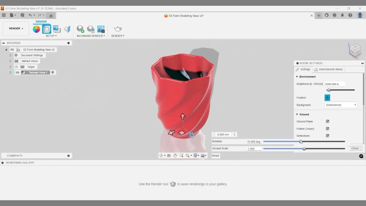
Environment lighting, reflections, and ground plane settings are adjusted in the Render workspace to control how light interacts with the vase surface and improve the realism of the final render.
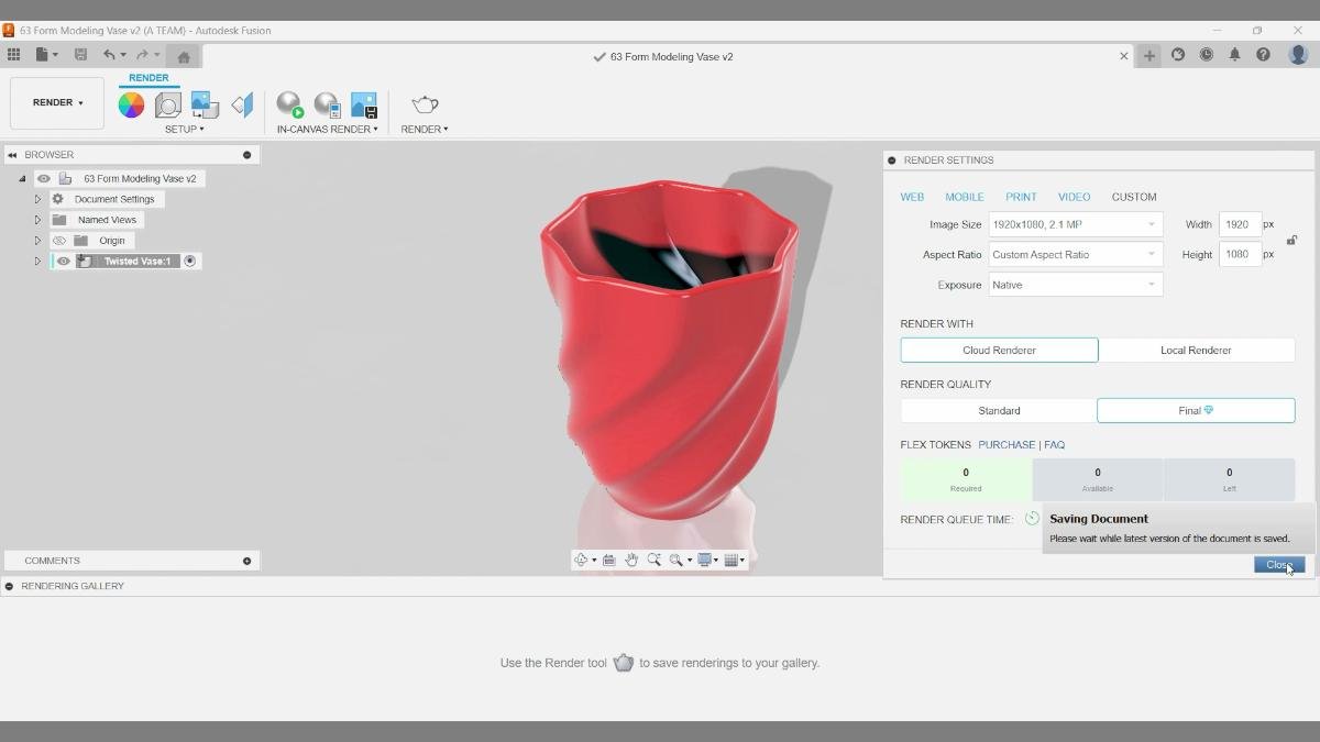
Render settings are configured for final output, including image resolution, aspect ratio, and render quality. Cloud rendering is selected to produce a higher-quality image without relying on local hardware.
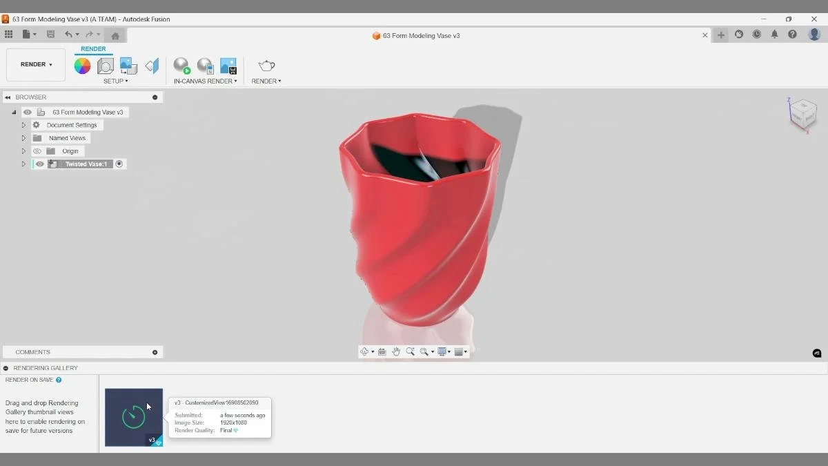
Render on save is active, and the rendering process is visible in the rendering gallery at the bottom left. The preview indicates the image is being generated with final quality settings using cloud rendering.
Key Takeaways
- Combining Form, Surface, and Solid modeling unlocks far more design flexibility in Fusion.
- Circular symmetry and Edit Form allow fast sculpting of rotational objects like vases.
- Surface models must be patched and stitched before they become printable solids.
- The Shell tool creates controlled wall thickness for 3D printing.
- Full Round Fillets help maintain smooth curvature while staying parametric.
- Cloud rendering is an efficient way to create high-quality images for presentations, thumbnails, or websites.
Mastering these workflows gives you far more control over complex designs and opens the door to creating professional-quality models ready for visualization or 3D printing.
🧰 Tools & Deals
I’ve gathered some of the tools, software, and gear I personally use and recommend for CAD work, 3D printing, and making things in one place. Some links may include discounts or special offers that can help you level up your workflows.
Please note: some of the links are affiliate links, which means I may earn a small commission at no extra cost to you. This helps support the site and the creation of free Fusion tutorials.
Explore everything here:
The Maker Letters – Tools & Deals
.
Chapters
- 00:10 — Setting Up a Component
- 00:21 — Creating a Cylinder in Form Mode
- 01:25 — Editing the Form Shape
- 02:30 — Twisting the Vase
- 03:50 — Closing Surfaces with Patch
- 04:22 — Converting to a Solid Model
- 04:48 — Making the Vase Hollow
- 05:06 — Adding a Parametric Chamfer
- 05:55 — Applying a Glossy Finish
- 06:23 — Rendering the Final Design
You Might Also Like
If you enjoyed this Fusion tutorial, here are three more projects that dive deeper into surface modeling, smooth geometry, and practical CAD workflows. These guides expand on the same ideas used in this vase project and show how surface and solid tools can be combined to create clean, 3D-printable designs.
Learn how to build smooth, curved geometry using Fusion’s surface modeling tools. This tutorial shows how to control curvature, refine edges, and convert surfaces into a clean solid body ready for 3D printing.
🏺 Fusion tutorial: Combine surface and solid modeling to design a vaseExplore a workflow that blends surface modeling with solid features to create elegant curved forms. This project demonstrates how different modeling environments in Fusion can work together to produce complex shapes efficiently.
🧴 Fusion tutorial: Model a bottle prototype with surface modelingFollow a step-by-step workflow for creating a smooth bottle prototype using Fusion’s surface tools. The tutorial focuses on controlling curvature, shaping organic forms, and preparing the model for visualization or product design workflows.
Together, these tutorials build on the same core principles used in the twisted vase project—creating smooth geometry, combining surface and solid modeling techniques, and turning CAD workflows into practical designs for 3D printing or product visualization.