How to Use the Honeycomb Pattern Add-In in Autodesk Fusion
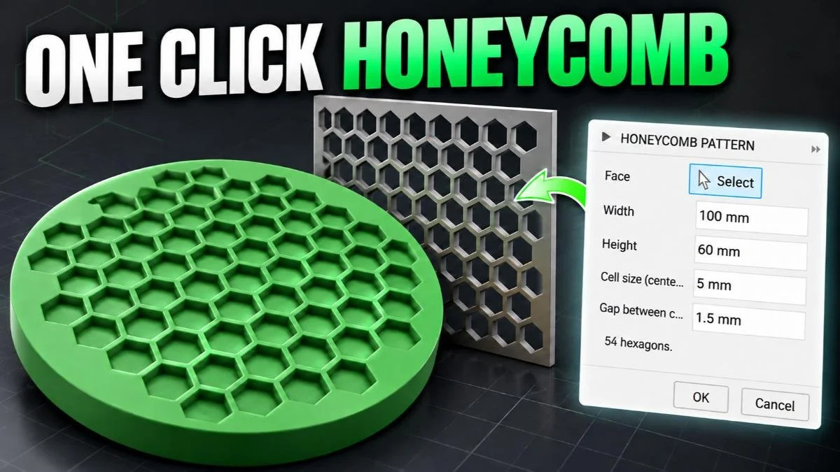
Drawing and positioning dozens of hexagons can turn a simple design detail into a repetitive modeling task. My Honeycomb Pattern Add-In for Autodesk Fusion (formerly Fusion 360) creates the pattern for you, with adjustable cell size, spacing, and edge margin. This tutorial shows how to use it on three different planar faces and directly in a sketch, then explains how to activate it.
Get the Add-in
https://themakerletters.gumroad.com/l/honeycomb-pattern-fusion
What You’ll Learn
- Create honeycomb patterns on circular, ring-shaped, and irregular planar faces.
- Adjust Cell Size, Gap Between Cells, and Edge Margin.
- Create a rectangular honeycomb grid in a sketch using Width and Height.
- Extrude the pattern and choose an appropriate modeling operation.
- Consider wall thickness, print orientation, and sketch complexity.
- Activate the add-in and enable Run on Startup.
Watch the Workflow — or Read It Step by Step
You can follow this guide in two ways:
- Read the steps below if you want quick written instructions, reference images, and modeling notes.
- Watch the full video at the end of this post to see the workflow in real time — including extra tips, camera angles, and shortcuts that don’t fit neatly into text.
Both formats build on each other.
Reading helps you understand why each step matters, while watching shows how to move faster in Fusion.
Step 1: Open the Honeycomb Pattern Add-In
In the Solid workspace, open the Create menu and select the Honeycomb add-in near the bottom.
Choose the planar face where you want to create the pattern. The tutorial demonstrates three examples:
- A circular face.
- A circular face with a hole in the middle.
- An irregular face.
These examples show how the same tool can generate patterns within different outlines.
Modeling note: The demonstrated workflow uses planar faces. A curved outer outline is different from a curved surface: an irregular shape can still have a flat face suitable for this workflow.
Open the Create menu in Fusion’s Solid workspace and select Honeycomb Pattern near the bottom. The command launches the add-in’s pattern settings.
The three bodies provide different planar boundaries for the demonstration: a circle, a ring, and an irregular outline with a hole.
Step 2: Adjust the Pattern on a Circular Face
Start with the circular face and adjust the available settings:
- Cell Size: Controls the size of the hexagonal cells.
- Gap Between Cells: Controls the spacing between neighboring cells.
- Edge Margin: Controls the clearance between the pattern and the face boundary.
The script does not specify numerical values for these settings, so choose them to suit your design and inspect the preview before confirming.
Select the circular face to define the pattern area. The displayed settings are Cell Size: 5 mm, Gap Between Cells: 1.5 mm, and Edge Margin: 2 mm, producing a preview of 65 hexagons.
With a face selected, the add-in uses its boundaries instead of separate Width and Height values. Edge Margin leaves clearance between the hexagons and the outer perimeter.
Once the pattern is ready, press E to open Extrude and enter the height or depth your project requires.
3D-printing note: If you extrude the hexagons as a cut, the material between the openings becomes the honeycomb structure. Inspect those remaining walls and the outer rim in your slicer. Very narrow sections may print poorly or provide less strength than you need.
For a flat part, printing with its broad face on the build plate is often a useful starting point because the walls grow vertically.
After creating the pattern, select the hexagonal profiles and press E to open Extrude. Set the extrusion distance to control how far the profiles extend into or away from the circular body.
For recessed cells, retain material beneath the cuts. Cutting through the full thickness produces openings instead, so the extrusion depth determines whether the result is a pocketed disc or a perforated panel.
Step 3: Create a Pattern Around a Central Hole
Next, select the circular face with a hole in the middle.
When an existing face is selected, Width and Height disappear from the dialog. The selected face’s boundaries define the area available for the honeycomb pattern.
In the demonstration, the default settings leave two isolated cells near the center. A small adjustment to Cell Size removes them and produces a cleaner arrangement.
Default settings will not suit every outline. The relationship between cell size and the available area affects which cells fit near a hole or edge.
Select the ring-shaped face to generate a pattern within its outer perimeter and around the central opening. The displayed settings are Cell Size: 4 mm, Gap Between Cells: 1.5 mm, and Edge Margin: 2 mm, with 74 hexagons in the preview.
The tutorial adjusts Cell Size to remove two isolated cells near the center. Small changes affect which hexagons fit between the inner and outer boundaries, helping refine the arrangement around the hole.
Once the arrangement looks right, confirm the pattern and press E to extrude it to the required height or depth.
3D-printing note: Pay attention to the material surrounding the central hole. If the hole serves a functional purpose, such as accepting a fastener, leave enough material around it for the expected load. A visually balanced pattern still needs adequate structural connections.
Use Extrude, available through the E shortcut, to turn the ring’s honeycomb profiles into a three-dimensional feature. Check the extrusion preview around the central hole before confirming.
The material between the cells and the hole forms an inner rim. If the opening has a functional purpose, such as accepting a fastener, consider the required strength when choosing the pattern spacing and margin.
Step 4: Fit the Honeycomb Pattern to an Irregular Face
Select the irregular planar face and adjust Cell Size, Gap Between Cells, and Edge Margin until the preview looks suitable.
The dialog displays a live preview and the total number of hexagons, helping you assess both the layout and its complexity.
A practical adjustment sequence is:
- Set Cell Size to establish the overall pattern density.
- Adjust Gap Between Cells to refine the spacing.
- Adjust Edge Margin to give the perimeter suitable clearance.
- Inspect narrow regions and cells near the boundary.
The irregular face is selected with Cell Size: 5 mm, Gap Between Cells: 1 mm, and Edge Margin: 2 mm. The highlighted preview count reports 95 hexagons.
Inspect the narrow waist and the area surrounding the hole as you adjust the settings. These local boundaries influence the arrangement even though the face is processed as one pattern area.
Confirm the pattern, then press E to extrude it.
Performance note: Large patterns create more sketch geometry. As with a manually drawn Fusion sketch, a very dense grid can slow editing and subsequent operations. Use enough detail for the design without adding cells that provide little practical benefit.
3D-printing note: Narrow portions of an irregular shape deserve particular attention. Check that the pattern leaves continuous material connecting those regions to the rest of the part.
Confirm the irregular pattern, then press E to extrude its profiles. Inspect the selected regions across both lobes and around the hole to ensure the intended cells are included.
The larger collection of profiles adds complexity to the operation. If editing becomes slow, increasing Cell Size can reduce the amount of sketch geometry while retaining the overall honeycomb appearance.
Step 5: Create a Honeycomb Pattern Directly in a Sketch
You can also create the pattern without selecting an existing face.
Start a sketch and open the Honeycomb add-in. In this mode, the pattern is centered on the sketch origin.
In an active sketch without a selected face, set Width: 100 mm and Height: 100 mm. The displayed Cell Size: 5 mm and Gap Between Cells: 1 mm produce 105 hexagons.
The grid is centered on the sketch origin. Width and Height define its overall area, allowing a rectangular pattern to be created independently of an existing body’s outline.
Because there is no selected face to define the boundaries, the dialog provides two additional controls:
- Width: Sets the overall width of the grid.
- Height: Sets the overall height of the grid.
Adjust these alongside the cell size and spacing, then confirm the pattern.
Centering the grid on the origin gives you a consistent reference for positioning it relative to other geometry.
The resulting sketch can be used just like one you drew manually. You can create features from its profiles and incorporate it into a larger design.
Step 6: Extrude the Sketch and Choose the Operation
Press E to open Extrude.
In the demonstration, the extrusion passes through an existing body, so Fusion suggests a Cut operation. This removes material from that body.
You can change the operation to New Body, or select another operation that suits the intended result. Check both the selected profiles and the operation before confirming.
The same honeycomb sketch can support different projects, including:
- A perforated panel for 3D printing.
- A laser-cut design.
- A 3D-printed mold for a concrete project.
Extrude the sketch profiles through an existing body and review the Operation menu. In the demonstrated workflow, Fusion initially suggests Cut because the extrusion intersects existing geometry.
Choose New Body when the selected profiles should form separate geometry instead of removing material. The operation changes the result even when the extrusion direction and distance remain the same.
3D-printing note: Through-openings and recessed pockets produce different results. For pockets, check the remaining floor thickness. For through-openings, inspect the connecting walls and perimeter.
Review the sliced model before printing. Layer preview can reveal thin sections, unsupported features, and gaps that are difficult to judge from the CAD view alone.
The finished rectangular grille demonstrates a honeycomb structure with through-openings and a surrounding frame. Its repeated cells originate from the rectangular sketch pattern.
For 3D printing, inspect the connecting walls in the slicer before printing. A flat orientation on the build plate lets the openings extend vertically through the part and avoids bridging across them.
Step 7: Activate the Honeycomb Pattern Add-In
After downloading the add-in, follow its included instructions to place the files in the correct folder.
In Fusion:
- Open Utilities.
- Open Add-Ins.
- Find Honeycomb Pattern in the list.
- Select it and click Run.
- Enable Run on Startup if you want it to load automatically whenever you open Fusion.
If the add-in does not appear, check the folder location against the supplied installation instructions.
The add-in is available through the link in the video description for a small fee, which supports the work involved in creating it.
To access the add-in controls, switch to Utilities in Fusion’s toolbar. This is the starting point for opening Scripts and Add-Ins.
Creating a pattern and managing the add-in use different menus: the pattern command is under Create, while activation is handled through Utilities.
Under Utilities, open the Add-Ins menu and select Scripts and Add-Ins. This opens the dialog used to manage installed scripts and add-ins.
If Honeycomb Pattern is missing from the list, check that its downloaded files were placed in the folder specified by the included installation instructions.
Locate HoneycombPattern in the Scripts and Add-Ins dialog and enable its Run control. The highlighted row shows the add-in running, while Run on Startup remains unchecked.
Enable Run on Startup if you want the add-in to load automatically when Fusion opens. Running it activates it for the current session; the startup setting controls automatic loading in future sessions.
Watch the Full Video
Watch the complete walkthrough to see the previews, parameter adjustments, and extrusion steps in real time.
Video chapters:
- 00:00 Introduction
- 00:10 Create a Honeycomb Pattern on a Solid Body
- 01:47 Create a Honeycomb Pattern in a Sketch
- 02:53 Activate the Honeycomb Add-In
Key Takeaways
- The Honeycomb Pattern Add-In creates hexagonal patterns on planar faces or directly in a sketch.
- Selected face boundaries define the pattern area; sketch mode uses Width and Height.
- Cell Size, Gap Between Cells, and Edge Margin help fit the pattern to different outlines.
- Small parameter changes can remove isolated cells and improve the arrangement.
- Press E to extrude, then check the selected profiles and modeling operation.
- For 3D printing, inspect the remaining walls, perimeter, floor thickness, and sliced result.
- Keep pattern complexity manageable and enable Run on Startup for convenient access.
🧰 Tools & Deals
I’ve gathered some of the tools, software, and gear I personally use and recommend for CAD work, 3D printing, and making things in one place. Some links may include discounts or special offers that can help you level up your workflows.
Please note: some of the links are affiliate links, which means I may earn a small commission at no extra cost to you. This helps support the site and the creation of free Fusion tutorials.
Explore everything here:
The Maker Letters – Tools & Deals
.
You Might Also Like
Want to explore more Fusion workflows for lighting design, surface modeling, and organic 3D printable geometry? These three tutorials build on the same techniques used in this lampshade project, including splines, patterns, revolves, and printable surface structures.
Each project focuses on practical Fusion workflows for organic modeling, surface control, and efficient 3D printable design techniques that translate well into real-world products and renders.