Master Fusion Techniques: Design an Intricate Bowl with Sheet Metal, Surface Modeling, and Loft Tools
Updated January 21, 2026
Hunter-gatherers never had access to Fusion — but if they did, they would probably follow the first rule of Fusion: start by creating a new component. In this project, we’ll design a decorative bowl by combining sheet metal and surface modeling workflows in Fusion. The goal isn’t mass production — it’s learning flexible techniques you can reuse in many future projects.
What You’ll Learn
In this tutorial, you’ll learn how to combine sheet metal and surface modeling in Fusion, how to reuse and link sketch geometry, when surface tools outperform solid tools, and how to build decorative features that stay editable and parametric throughout the design process.
Watch the Workflow — or Read It Step by Step
You can follow this guide in two ways:
- Read the steps below if you want quick written instructions, reference images, and modeling notes.
- Watch the full video at the end of this post to see the workflow in real time — including extra tips, camera angles, and shortcuts that don’t fit neatly into text.
Both formats build on each other.
Reading helps you understand why each step matters, while watching shows how to move faster in Fusion.
Step 1: Create a New Component and Base Sketch
Start by creating a new component. This keeps the timeline clean and makes it easier to edit or reuse the design later.
The first sketch defines the foundation of the bowl. Instead of fully committing to a closed solid, we deliberately trim away part of a circle and extend a section to the side. This workaround gives us more freedom later when we introduce taper and lofted geometry. At this stage, precision matters less than setting up flexibility.
A new internal component is created in Fusion before any geometry is added. Starting with a clean component keeps the timeline organized and makes later edits, surface work, and sheet metal operations easier to manage as the bowl design evolves.
The first sketch establishes the bowl’s footprint. Instead of a complete circle, part of the profile is trimmed and extended to one side. This creates a more flexible foundation that works better with taper, lofted sheet metal, and later surface modeling steps.
Step 2: Set Up an Offset Construction Plane
An offset plane is created early because it enables a sheet metal loft with a taper angle. By thinking ahead and placing reference geometry now, we avoid rebuilding the model later. This is a common Fusion habit that pays off in complex workflows.
An offset construction plane is placed above the base sketch early in the workflow. This reference plane makes it possible to create a tapered sheet metal loft later without rebuilding geometry, which is a common time-saving strategy in more complex Fusion projects.
Step 3: Reuse Geometry with the Project Command
Rather than redrawing geometry, use the Project command to reuse edges from the base sketch. Projected geometry appears in purple, making it easy to identify linked elements.
The advantage here is parametric behavior: if the original sketch changes, every projected line updates automatically. This keeps the model robust and reduces future rework.
The Project command is used to bring existing sketch geometry into a new sketch. Projected curves appear in purple, indicating that they are linked to the original sketch and will update automatically if the base geometry changes, keeping the bowl fully parametric.
The Offset command is used to create a secondary curve at a fixed distance from the projected geometry. This offset defines the bowl’s wall thickness in the sketch and ensures the profile remains consistent and easy to adjust later in the timeline.
Step 4: Create a Lofted Flange in Sheet Metal
Switch to the Sheet Metal workspace and use a Lofted Flange. This tool is ideal when you want controlled taper while keeping sheet metal rules intact.
At this stage, we’re not designing for manufacturing — this is rapid concept modeling. The goal is to explore shape and proportion, not optimize bend allowances or tooling.
The Lofted Flange tool in the Sheet Metal workspace is used to create the main bowl form with controlled taper. This approach keeps sheet metal rules intact while allowing fast experimentation with shape and proportion during early concept modeling.
Step 5: Edit the Flange Using the Timeline
Fusion’s timeline makes experimentation safe. If you want a different visual style, you can edit the flange feature and switch the forming type to a Die Form. This flexibility is why timeline-based modeling is so powerful for concept design.
The existing lofted flange is edited directly in the timeline and the forming type is changed to Die Form. This small change alters the visual character of the bowl without rebuilding geometry, demonstrating the flexibility of Fusion’s timeline-based modeling workflow.
Step 6: Unfold the Bowl Correctly
When unfolding sheet metal, orientation matters. Make sure you’re working on the correct side of the bowl. In this case, the features are created on the back side — opposite the Home view in the view cube.
Getting this right now prevents mirrored or inverted details later.
The bowl is unfolded using a selected stationary face. Choosing the correct side is critical, since all decorative sketch work will be created on this flat state before the sheet metal is refolded back into its tapered shape.
With all bends unfolded, the sheet metal body is laid out flat. This flat state provides a clean, predictable surface for inserting SVG artwork and creating decorative sketches before the bowl is refolded back into its final form.
Step 7: Insert and Position a Licensed SVG
Insert a licensed SVG to create the hunter-gatherer figures. Using licensed artwork is a great way to combine your Fusion skills with the work of talented illustrators.
Scale and position the SVG roughly. Precision isn’t required yet — this is another example of delaying perfection until the design context is clearer. This is also why we avoided embossing on a tapered solid earlier and kept the design flat during this stage.
A licensed SVG illustration is inserted onto the unfolded sheet metal surface. The artwork is roughly scaled and positioned without aiming for precision yet, allowing the decorative layout to evolve naturally before final alignment and detailing.
Step 8: Remove Constraints and Clean Up the Sketch
Green geometry indicates a Fix Constraint. Remove it so each figure can be positioned independently.
While cleaning the sketch, trim away unnecessary segments. A useful Fusion trick here is pressing and holding while trimming — it makes sketch cleanup significantly faster.
The imported SVG figures are laid out across the flat sheet metal surface. At this stage, the focus is on overall spacing and rhythm rather than exact positioning, allowing the decorative motif to be adjusted easily before refolding the bowl.
Step 9: Position the Figures Using Construction Geometry
Stay in the contextual sketch environment while repositioning sketches. Don’t aim for perfection immediately. Place elements roughly, confirm with OK, and refine later.
This iterative approach keeps momentum high without sacrificing accuracy.
Step 10: Use Construction Lines for Symmetry
Project a reference line from the underlying geometry and convert it to a construction line. This acts as a visual guide to align figures symmetrically around the bowl.
Because everything is linked, adjustments remain predictable and easy to manage.
Step 11: Extrude and Refold the Sheet Metal
Select all sketch profiles and extrude them using the Join operation. This refolds the geometry back into the original component, keeping the model unified and editable.
The hunter-gatherer figures are selected as sketch profiles and extruded using the Join operation. This refolds the decorative geometry into the sheet metal body, creating raised details that remain fully editable through the timeline.
Step 12: Apply Initial Appearances
Applying appearances at this stage makes visual evaluation easier. Start with a preset appearance and adjust color values for balance and contrast.
At first, assigning appearances individually feels logical — until you reach more complex areas like the sides.
Base appearances are applied to the unfolded sheet metal body to evaluate contrast between the bowl surface and the raised decorative figures. Assigning colors at this stage makes it easier to judge proportions and visual balance before continuing with further modeling steps.
Step 13: Use a Faster Appearance Workflow
A faster method is to color the entire body first, then apply a contrasting color to selected faces. Duplicate and name appearances to keep things organized.
Be mindful of the “Apply To” setting. Switching between bodies and faces is essential for this workflow to succeed.
Step 14: Refold and Continue the Bowl Shape
With the decorative work complete, refold the sheet metal and return to shaping the bowl itself.
Step 15: Extrude Cut and Quality Check
Extrude is equally powerful for removing material. Setting the Extent Type to All ensures the cut remains valid even if dimensions change later.
Regularly rotate the model and inspect it from different angles. Catching small issues early saves time later.
An extrude cut is applied to remove excess material along the side of the bowl. Setting the extent type to All ensures the cut remains valid and updates correctly even if the bowl’s dimensions change later in the timeline.
Step 16: Sketch the Bottom Geometry
Project the outer edge of the bowl and add a center diameter circle to close the shape. Because the geometry spans only part of a full circle, the dimensions may differ from the original 100 mm sketch — this is expected due to sheet metal thickness and taper.
The inner edge of the bowl is projected into a new sketch to reuse existing geometry. This projected curve becomes the reference for closing the bottom later, ensuring the sketch stays linked and updates automatically if the bowl shape changes.
Step 17: Repeat the Bottom Sketch on the Offset Plane
Repeat the process on the offset construction plane created earlier. Selecting the correct plane is critical so the bottom geometry aligns correctly in height.
Viewed from above, the bowl’s opening geometry is projected into a sketch. This sketch defines the circular footprint used for closing the bottom later and highlights how the sheet metal taper and thickness affect the final dimensions compared to the original base sketch.
Step 18: Loft Using Surface Modeling
Use the Loft command from the Surface workspace. The orange icon helps distinguish it from the solid loft tool.
Surface lofts are ideal here because they allow smooth transitions without forcing solid constraints too early.
A loft is created between the projected bottom profile and the upper opening of the bowl. This step rebuilds the wall geometry in a controlled way and prepares the model for surface-based refinement and bottom closure.
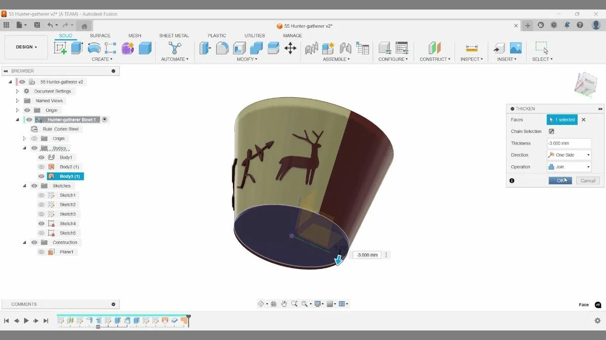
Step 19: Thicken the Surface
The lofted surface has zero thickness. Use the Thicken command to match the bowl’s wall thickness and set the operation to Join so the model remains a single body.
The lofted surface is given thickness using the Thicken command. Setting the operation to Join merges the surface with the existing geometry, resulting in a solid bowl wall while preserving the smooth surface transitions created earlier.
Step 20: Close the Bottom with Patch
Patch is perfect for closing open surfaces. Once patched, thicken the surface and join it with the rest of the bowl to create a watertight model.
The Patch command is used to close the open bottom of the bowl by selecting the boundary edge. This creates a clean surface that can be thickened and joined, resulting in a watertight model ready for further refinement or 3D printing.
The patched bottom surface is thickened to match the wall thickness and joined with the rest of the bowl. This step completes the solid geometry and ensures the model is watertight and suitable for rendering or 3D printing.
Step 21: Apply Final Colors and Edge Treatment
Reapply the lighter color to the bottom face. For the edge, both fillet and chamfer are valid options. In this case, a chamfer provides a cleaner visual transition, but the timeline makes it easy to switch later.
Final appearances are applied to the solid bowl, with a lighter exterior and a darker interior for contrast. Adjusting colors at the end helps evaluate the overall form, edge transitions, and decorative details as a complete design.
A chamfer is applied to the bottom edge of the bowl to soften the transition between the wall and the base. This edge treatment improves both the visual finish and the tactile feel, while remaining easy to adjust later through the timeline.
Step 22: Evaluate Full Round Fillets
Full round fillets are excellent for parametric edge control, as they adapt automatically when thickness changes. In this project, however, the fillet didn’t improve the design — an important reminder that not every “correct” tool fits every situation.
A full round fillet is evaluated on the top edge of the bowl. This type of fillet adapts automatically to thickness changes, but in this case it doesn’t improve the visual result—highlighting that even powerful parametric tools aren’t always the best design choice.
Step 23: Sketch the Curved Top Profile
Create a sketch in the central construction plane using a fit point spline. Splines offer flexibility and are ideal for organic shapes.
Over-sketch intentionally. Surface modeling allows you to refine geometry later without committing too early.
A fit point spline is sketched in the central construction plane to control the curvature of the bowl’s top edge. This profile is intentionally over-sketched, allowing the final shape to be refined later using surface modeling tools without committing too early to a fixed form.
Step 24: Extrude the Surface Symmetrically
Use the surface extrude, not the solid one. Switch to a symmetric extrude and overbuild the surface slightly. This surface acts as a tool, not final geometry.
A surface is extruded symmetrically from the spline sketch and used as a cutting tool with Split Body. The result isn’t immediately obvious, but a new body is created in the browser, allowing unwanted geometry to be hidden and revealing the refined bowl shape.
Step 25: Split the Bowl with Split Body
Use Split Body to cut the bowl using the curved surface. The result won’t be obvious immediately, but a new body appears in the browser. Hide the unnecessary bodies to reveal the final form.
The Split Body command uses the curved surface as a cutting tool to refine the bowl’s final silhouette. After hiding the excess bodies, the remaining geometry reveals the completed form produced by combining sheet metal, surface modeling, and solid workflows in Fusion.
Key Takeaways
- Start with flexible geometry, not final shapes
- Use Project to maintain parametric relationships
- Sheet metal tools are excellent for controlled taper
- Surface modeling enables fast, non-destructive exploration
- The timeline makes experimentation safe
- Not every tool improves every design — evaluate critically
If you found this useful, check the video description for additional resources and related Fusion tutorials.
🧰 Tools & Deals
I’ve gathered some of the tools, software, and gear I personally use and recommend for CAD work, 3D printing, and making things in one place. Some links may include discounts or special offers that can help you level up your workflows.
Please note: some of the links are affiliate links, which means I may earn a small commission at no extra cost to you. This helps support the site and the creation of free Fusion tutorials.
Explore everything here:
The Maker Letters – Tools & Deals
.
⏱ Chapters
- 00:03 How to create a new component in Autodesk Fusion
- 00:14 How to make a circle in Fusion
- 00:24 How to trim a sketch in Fusion
- 00:40 How to create an Offset Plane in Fusion
- 00:52 Project a sketch in Fusion
- 01:20 Lofted Flange in Fusion
- 01:36 Flange Sheet Metal Settings Fusion
- 01:51 How to flatten warped sheet metal in Fusion
- 02:09 How to insert SVG in Fusion?
- 02:26 Fusion Scale SVG after Import
- 02:45 Why is my sketch locked in Fusion?
- 02:55 Trim multiple lines Fusion tutorial
- 03:09 Why can’t I move my sketch in Fusion?
- 04:15 How to extrude in Autodesk Fusion?
- 04:34 Add appearance with Hex Code in Fusion
- 05:35 How do you add custom colors in Fusion?
- 06:38 Refold Sheet Metal in Fusion
- 06:54 Extrude through all objects Fusion
- 08:28 How to loft two circles in Fusion
- 08:39 How to make a surface thick in Fusion
- 08:56 How to patch a surface in Fusion
- 09:42 Chamfer an edge in Fusion
- 10:43 How to cut out shape in Fusion
- 11:13 Extrude a spline in Fusion
- 11:40 How to split a body in Fusion
You Might Also Like
If you enjoyed this Fusion tutorial, here are three more projects that dive deeper into curved patterns and advanced surface techniques — perfect if you're exploring decorative designs.
These tutorials each show a different approach — from surface-driven curves to solid-body precision — helping you master the tools you need for professional-quality 3D-printable designs.