How to add User Parameters in Fusion
Updated November 26, 2025
If you design for 3D printing, you already know the power of speed. The faster you can adjust dimensions and test size variations, the faster you get a model ready for the real world. Parametric dimensions in Fusion give you exactly that advantage—change one number, and your entire model adapts instantly.
In this project, we’ll build a simple box with a lid and a handle. The design itself is basic, but the workflow teaches you one of the most powerful skills in CAD: creating flexible, scalable models that hold their proportions no matter how large or small you make them.
What You’ll Learn
You’ll learn how to:
- Build a fully parametric model using User Parameters
- Use Center Rectangle for clean alignment and predictable updates
- Apply Shell to create a perfectly controlled wall thickness
- Drive multiple features from one core dimension
- Test your design by changing a single parameter and watching the geometry adapt
Each tool is used for a reason, and I’ll explain why these choices improve speed, precision, and long-term flexibility.
Step 1 — Set Up Your User Parameters
Creating parameters is how we make this model fully adjustable. Begin with:
- BoxLength — the core driver of the entire model
- Other parameters like height, width, lid size, and handle size tied mathematically to BoxLength
- One independent parameter for BoxThickness, giving full control over the wall thickness
The advantage of setting a single driving parameter is simple: you can test ten different box sizes in seconds.
Fusion immediately calculates and displays the resulting values in the table, confirming that your formulas are correct
Creating a new user parameter for HandleWidth makes the handle scale automatically with the rest of the box. Defining it with a direct expression keeps the design fully parametric, which reduces manual edits when BoxLength or BoxWidth change.
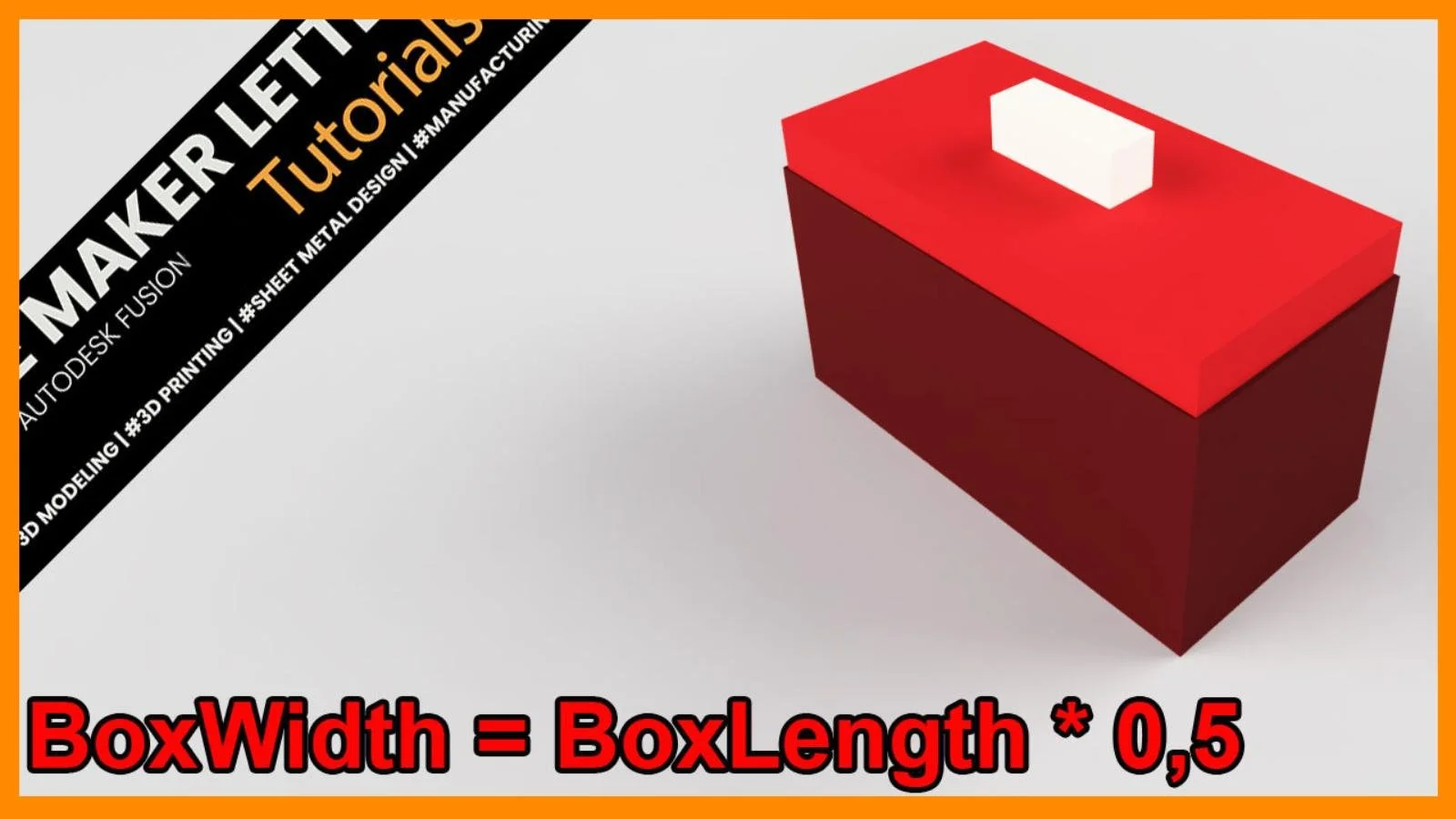
The parameters are linked through expressions such as BoxLength 0.5 and BoxLength 0.98. Using proportional relationships maintains consistent proportions across the model and prevents distortion when the primary length value is adjusted.
Step 2 — Sketch the Base Using Center Rectangle
Use Center Rectangle to sketch the footprint of the box.
Why this tool? Because centering your model on the origin keeps everything symmetric and predictable when parameters update later.
- Draw the rectangle from the origin
- Enter your user parameter expressions directly into the dimension fields
- Press Tab to jump quickly between inputs
This is efficient modeling: fast inputs, full control, and no manual repositioning.
Extrude the base upward and assign the BoxHeight parameter. The body now scales perfectly with your numbers.
The base rectangle is fully dimensioned using BoxLength and BoxWidth. Locking the sketch to parametric values ensures all downstream features update accurately when dimensions change.
The profile is extruded using BoxHeight to maintain a consistent wall height. Selecting parameters directly in the dialog keeps the feature dependent on the parameter table instead of static values, which preserves editability later in the workflow.
Step 3 — Hollow the Box Using Shell
Apply Shell to the top face and enter the BoxThickness parameter.
Shell is the ideal tool here because:
- It creates uniform wall thickness
- It maintains the interior cavity shape perfectly
- It updates cleanly when parameters change
This is the only parameter in the project not tied to BoxLength, giving you freedom to adjust thickness independently
The Shell command applies BoxThickness to create uniform wall thickness. Connecting shell thickness to a parameter prevents errors when scaling the model, since the internal cavity adjusts automatically without manual recalculation.
Step 4 — Create the Lid
Sketch another Center Rectangle—this time directly on top of the box.
Because the original body is centered on the origin, this sketch lands exactly where it should. No shifting, no aligning, no guesswork.
Using clearly named parameters makes selecting the correct dimension relationships straightforward and error-free.
Extrude the lid to the height defined in your parameter list.
The lid height is driven by the LidHeight parameter, allowing the lid to maintain proportional thickness relative to the main box. Using a parametric value avoids mismatches between lid and body when BoxLength is modified.
Step 5 — Add a Parametric Handle
Sketch the handle on top of the lid.
Again, the central alignment makes things easy. Repeat the workflow:
- Sketch from the origin
- Input your handle parameters
- Extrude
Fusion suggests a Join operation when extruding—this is fine for a quick demonstration.
But in real product development, you may prefer New Body or New Component for maximum flexibility. The choice depends on whether you want the handle fused or kept separate for printing or assembly.
The handle’s proportions are controlled through parameters, making the handle scale cleanly with the rest of the design.
Step 6 — Put the Design to the Test
Open the User Parameters window.
Change the BoxLength value.
Everything updates—the sketch, the lid, the handle, the shell thickness, the proportions. It’s instant. It’s clean. And the parameter table shows the exact updated values.
This is the power of parametric modeling: one change, complete adaptation.
Accessing Change Parameters through the shortcuts menu speeds up iteration. Fast access to the parameter table is useful when adjusting dimensions repeatedly, especially in parametric workflows that rely on testing multiples values.
Changing BoxLength updates all dependent expressions, scaling the box, lid, and handle automatically. This demonstrates the core benefit of parametric modeling: one edit drives multiple features without breaking constraints or creating misalignment.
Key Takeaways
- User Parameters make your model scalable, editable, and future-proof.
- Center Rectangle keeps everything aligned and removes the need for manual repositioning.
- Shell ensures consistent wall thickness with zero extra calculations.
- Named parameters + expressions keep your model readable and easy to build on.
- One driving dimension (BoxLength) lets you test designs fast and with confidence.
If you're improving your CAD workflow for 3D printing, these habits will save hours—not once, but every time you open Fusion.
You Might Also Like
If you enjoyed this Fusion tutorial, here are three more projects that deepen your skills in sketch editing, surface–solid workflows, and advanced fillet techniques — essential tools for creating clean, reliable, and professional 3D-printable designs.
These tutorials highlight three core workflows — sketch editing, surface–solid blending, and fillet refinement — giving you the tools needed to build cleaner geometry and more reliable 3D-printable designs.